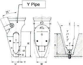
In the vis setter “Handy”, the screws are automatically supplied, gripped in the Y pipe (driver tip) and jaws, and tightened completely. Selecting the right type of Y pipe to match the shape of the work is essential.
Check the following items and select the right type of screw fastener.
Y pipe screw fastener space
Head shapes
| Small screws | Wood screws | ||||||||||
|---|---|---|---|---|---|---|---|---|---|---|---|
| A | B1 | B2 | C | A | B1 | ||||||
| Pan | Round | FlatCylinder | Fillister | Flat | Oval | Binding | Brazier | Truss | Round | Flat | Oval |
Driver tip sizes and tightening space
| Item | Screw type and size | Driver (Y pipe) tip sizes | Tightening space | ||||||||||||||||
|---|---|---|---|---|---|---|---|---|---|---|---|---|---|---|---|---|---|---|---|
| Model 40S | Model 35 | See driver units | A | B1 | B2 | C | φD1 | φD2 | R | S | T | U | W | Y | X | E | F | H | |
| M2.5 | ○ | ○ | ○ | 32 | 26 | 43 | 18 | 8 | 10 | 15 | 3 | 0.5 | 28 | 14 | 26 | ||||
| M3 | ○ | ○ | ○ | ||||||||||||||||
| 2.7(Wood screw) | ○ | ○ | 48 | 23 | |||||||||||||||
| 3.1(Wood screw) | ○ | ○ | 16 | ||||||||||||||||
| M3 | ○ | 29 | 47 | 19 | 10 | 12 | 1 | 32 | 16 | 28 | |||||||||
| Model 40 | M4 | ○ | ○ | ○ | 29 | 10 | 12 | 18 | |||||||||||
| 3.1(Wood screw) | ○ | ○ | 26 | 48 | 23 | 8 | 10 | 16 | 0.5 | 28 | 14 | 26 | |||||||
| 3.5(Wood screw) | ○ | ○ | 29 | 51 | 10 | 12 | 18 | 1 | 32 | 16 | 28 | ||||||||
| M4 | ○ | 32 | 50 | 18 | 11 | 13 | 22 | 34 | 16 | 34 | |||||||||
| Model 50 | M5 | ○ | 35 | 33 | 53 | ||||||||||||||
 W indicates dimensions when the jaw is fully opened during screw tightening.
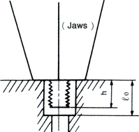
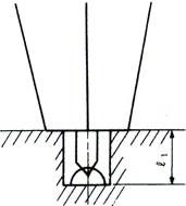
Tightening countersunk
A protrusion length h of 1 ℓ0+1 mm is required for countersunk sections.

A bit protrusion length ℓ1 is required when tightening as shown in the figure. The bit protrusion length depends on factors such as the driver model and Y pipe model so consult us for advice when countersunk (flush) sections must be tightened.

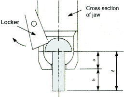
Jaw screw grip dimensions (chucking margin)


<Example> M3 X 15 L pan-head screws (30A)
h = 15 - 4 = 11 mm
- For Sems (with spring-washers) set the bottom length from the washer as ℓ.
- In wood screws, the rocker doesn't usually move. Dimensions are listed for rocker.
| Screw type | a mm | |
|---|---|---|
| M2.6 | A | 4.5 |
| B1 | 5 | |
| B2 | 4.5 | |
| 2.7(Wood screw) | A | 9 |
| B1 | 10.5 | |
| M3 | A | 4 |
| B1 | 5 | |
| B2 | 4.5 | |
| C | 5 | |
| 3.1(Wood screw) | A | 9 |
| B1 | 10.5 | |
| 3.5(Wood screw) | A | 8.5 |
| B1 | 10.5 | |
| M4 | A | 4 |
| B1 | 5.5 | |
| B2 | 4 | |
| C | 6 | |
| M5 | A | 5 |
| M6 | A | 7.5 |


